Crystek低抖動有源晶體振蕩器,全球頂尖供應商之一的Crystek公司,也是一家高性能技術領域的全球領導者無線電頻率(radio frequency)微波和頻率控制工業,Crystek Corporation一直提供頻率產品,包括石英晶體、XOs(時鐘石英晶體振蕩器)、TCXOs(溫度補償晶體振蕩器)、VCO(壓控振蕩器)和VCXOs(壓控晶體振蕩器)等元器件,Crystek Corporation的廣泛產品包括各種終端市場,包括無線、微波無線電、電信、工業、企業、航空航天和政府部門。

許多工程師在設計振蕩器電路時,并沒有在石英晶體上花太多心思。對他們來說,這是一個標準的功能,無論如何都會起作用。其實沒那么簡單。
振蕩器電路決定著應用的心跳,需要石英晶體和其它元件之間的仔細匹配。否則,所產生頻率的準確性會受到影響,應用甚至可能在現場失敗。
我們Crystek希望讓我們的客戶免受此類問題的困擾。因此,我們對客戶的振蕩器電路進行詳細分析,旨在實現晶體和電路的最佳匹配。在這些所謂的“OSF試驗”過程中檢查了以下三個參數:
1)頻率精度
2)振蕩安全系數(OSF)
3)驅動水平
振蕩器電路的主要任務是在整個應用周期和所有環境條件下產生穩定而精確的頻率。為了使總負載電容(CL)必須盡可能接近額定負載電容(額定CL)或理想地與之匹配。
因此,電路分析的第一步是確定總負載電容(CL)石英晶體在其兩端“看到”的。由于與電路的任何直接接觸都會使測量結果失真,因此測量是在不接觸的情況下進行的,使用近場探頭放置在電路上方一小段距離處。然后將晶體從電路中焊接出來,用晶體網絡分析儀在標稱溫度下測量L.
總C的偏差越大L從名義上的CL晶體的頻率偏差越大。然而,通過檢查分析儀中的晶體,可以確定需要哪些校正來提高電路的頻率精度。
在第二步中,檢查OSC振蕩器電路的振蕩安全性。該術語描述了電路在所有可能的環境條件下快速可靠啟動的能力。因此,分析的重點是電路中的電阻。
如圖1所示,電路中內置了一個新的附加電阻(R Pot ),與石英串聯。然后逐步增加R電位計的電阻,直到振蕩停止。這種方法模擬“最差情況下的石英”,并揭示特定振蕩器電路中石英的最大容許阻抗。
圖1:典型振蕩電路(Pierce配置),帶有一個額外的電阻來計算OSF
以這種方式確定的最大阻抗與晶體的ESR,max之比最終得出振蕩安全系數(OSF)。
對于MHz晶體(AT切割)對于大多數標準應用,大于5的OSF被認為是足夠的。對于與安全相關的應用,例如汽車行業或醫療技術,通常要求OSF大于10。
對于KHz晶振,OSF值在3到5之間就已經被評為良好,大于5的則被評為非常好,這是因為這些電路的設計功耗非常低。
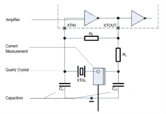
為了防止石英過載,需要確定是哪種功率作用在石英上。為此,第一步是使用高頻電流鉗測量流經石英的電流強度(圖2)。從這個測量結果和已經確定的電路參數計算石英的“驅動電平”。驅動電平不得超過石英數據表中規定的最大值。Crystek低抖動有源晶體振蕩器
圖2:為了計算驅動水平,測量流過石英晶體的電流。
超過最大驅動電平可能會導致頻率偏差,或者在最糟糕的情況下,甚至會導致石英發生故障。
通過所有三項測試的有源晶體振蕩器電路可以放心地集成到目標應用中。但是,如果測試顯示有缺陷,則必須調整電路。例如,如果頻率精度有問題,電路中負載電容的變化可以減小電路CL和標稱CL從而提高頻率精度。有時也需要將原來安裝的晶體更換為另一種類型。
對電路的任何改動都意味著必須重新進行這里列出的所有測試。這使得尋找石英和電路之間的完美匹配成為一項需要幾個小時的修補工作。由于組件的尺寸很小,許多工作都是在顯微鏡下完成的。
原廠代碼
品牌
型號
類型
頻率
頻率穩定度
工作溫度
C3390-40.000
Crystek振蕩器
C33
XO (Standard)
40MHz
±100ppm
0°C ~ 70°C
C3390-44.736
Crystek振蕩器
C33
XO (Standard)
44.736MHz
±100ppm
0°C ~ 70°C
C3390-45.000
Crystek振蕩器
C33
XO (Standard)
45MHz
±100ppm
0°C ~ 70°C
C3390-49.152
Crystek振蕩器
C33
XO (Standard)
49.152MHz
±100ppm
0°C ~ 70°C
C3390-50.000
Crystek振蕩器
C33
XO (Standard)
50MHz
±100ppm
0°C ~ 70°C
C3390-51.840
Crystek振蕩器
C33
XO (Standard)
51.84MHz
±100ppm
0°C ~ 70°C
C3390-6.176
Crystek振蕩器
C33
XO (Standard)
6.176MHz
±100ppm
0°C ~ 70°C
C3390-7.372800
Crystek振蕩器
C33
XO (Standard)
7.3728MHz
±100ppm
0°C ~ 70°C
C3390-8.000
Crystek振蕩器
C33
XO (Standard)
8MHz
±100ppm
0°C ~ 70°C
C3390-8.064
Crystek振蕩器
C33
XO (Standard)
8.064MHz
±100ppm
0°C ~ 70°C
C3390-8.192
Crystek振蕩器
C33
XO (Standard)
8.192MHz
±100ppm
0°C ~ 70°C
C3392-1.544
Crystek振蕩器
C33
XO (Standard)
1.544MHz
±50ppm
0°C ~ 70°C
C3392-1.843200
Crystek振蕩器
C33
XO (Standard)
1.8432MHz
±50ppm
0°C ~ 70°C
C3392-10.000
Crystek振蕩器
C33
XO (Standard)
10MHz
±50ppm
0°C ~ 70°C
C3392-12.000
Crystek振蕩器
C33
XO (Standard)
12MHz
±50ppm
0°C ~ 70°C
C3392-12.288
Crystek振蕩器
C33
XO (Standard)
12.288MHz
±50ppm
0°C ~ 70°C
C3392-12.352
Crystek振蕩器
C33
XO (Standard)
12.352MHz
±50ppm
0°C ~ 70°C
C3392-14.318180
Crystek振蕩器
C33
XO (Standard)
14.31818MHz
±50ppm
0°C ~ 70°C
C3392-15.360
Crystek振蕩器
C33
XO (Standard)
15.36MHz
±50ppm
0°C ~ 70°C
C3392-16.0000
Crystek振蕩器
C33
XO (Standard)
16MHz
±50ppm
0°C ~ 70°C
C3392-16.384
Crystek振蕩器
C33
XO (Standard)
16.384MHz
±50ppm
0°C ~ 70°C
C3392-18.432
Crystek振蕩器
C33
XO (Standard)
18.432MHz
±50ppm
0°C ~ 70°C
C3392-19.440
Crystek振蕩器
C33
XO (Standard)
19.44MHz
±50ppm
0°C ~ 70°C
C3392-2.048
Crystek振蕩器
C33
XO (Standard)
2.048MHz
±50ppm
0°C ~ 70°C
C3392-20.000
Crystek振蕩器
C33
XO (Standard)
20MHz
±50ppm
0°C ~ 70°C
C3392-20.480
Crystek振蕩器
C33
XO (Standard)
20.048MHz
±50ppm
0°C ~ 70°C
C3392-24.000
Crystek振蕩器
C33
XO (Standard)
24MHz
±50ppm
0°C ~ 70°C
C3392-24.576
Crystek振蕩器
C33
XO (Standard)
24.576MHz
±50ppm
0°C ~ 70°C
C3392-24.704
美國瑞斯克晶振
C33
XO (Standard)
24.704MHz
±50ppm
0°C ~ 70°C
C3392-25.000
Crystek振蕩器
C33
XO (Standard)
25MHz
±50ppm
0°C ~ 70°C
C3392-3.686400
Crystek振蕩器
C33
XO (Standard)
3.6864MHz
±50ppm
0°C ~ 70°C
C3392-30.000
Crystek振蕩器
C33
XO (Standard)
30MHz
±50ppm
0°C ~ 70°C
C3392-32.000
Crystek振蕩器
C33
XO (Standard)
32MHz
±50ppm
0°C ~ 70°C
C3392-32.768
Crystek振蕩器
C33
XO (Standard)
32.768MHz
±50ppm
0°C ~ 70°C
C3392-33.000
Crystek振蕩器
C33
XO (Standard)
33MHz
±50ppm
0°C ~ 70°C
C3392-33.333
Crystek振蕩器
C33
XO (Standard)
33.333MHz
±50ppm
0°C ~ 70°C
C3392-34.368
Crystek振蕩器
C33
XO (Standard)
34.368MHz
±50ppm
0°C ~ 70°C
C3392-35.000
Crystek振蕩器
C33
XO (Standard)
35MHz
±50ppm
0°C ~ 70°C
C3392-35.328
Crystek振蕩器
C33
XO (Standard)
35.328MHz
±50ppm
0°C ~ 70°C
C3392-4.000
Crystek振蕩器
C33
XO (Standard)
4MHz
±50ppm
0°C ~ 70°C
C3392-4.096
Crystek振蕩器
C33
XO (Standard)
4.096MHz
±50ppm
0°C ~ 70°C
C3392-40.000
Crystek振蕩器
C33
XO (Standard)
40MHz
±50ppm
0°C ~ 70°C
C3392-44.736
Crystek振蕩器
C33
XO (Standard)
44.736MHz
±50ppm
0°C ~ 70°C
C3392-45.000
Crystek振蕩器
C33
XO (Standard)
45MHz
±50ppm
0°C ~ 70°C
C3392-49.152
Crystek振蕩器
C33
XO (Standard)
49.152MHz
±50ppm
0°C ~ 70°C
C3392-50.000
Crystek振蕩器
C33
XO (Standard)
50MHz
±50ppm
0°C ~ 70°C
C3392-51.840
Crystek振蕩器
C33
XO (Standard)
51.84MHz
±50ppm
0°C ~ 70°C
C3392-6.176
Crystek振蕩器
C33
XO (Standard)
6.176MHz
±50ppm
0°C ~ 70°C
C3392-7.372800
Crystek振蕩器
C33
XO (Standard)
7.3728MHz
±50ppm
0°C ~ 70°C
C3392-8.000
Crystek振蕩器
C33
XO (Standard)
8MHz
±50ppm
0°C ~ 70°C
C3392-8.064
Crystek振蕩器
C33
XO (Standard)
8.064MHz
±50ppm
0°C ~ 70°C
C3392-8.192
Crystek振蕩器
C33
XO (Standard)
8.192MHz
±50ppm
0°C ~ 70°C
C3392-60.000
Crystek振蕩器
C33
XO (Standard)
60MHz
±50ppm
0°C ~ 70°C
C3392-64.000
Crystek振蕩器
C33
XO (Standard)
64MHz
±50ppm
0°C ~ 70°C
C3392-66.000
Crystek振蕩器
C33
XO (Standard)
66MHz
±50ppm
0°C ~ 70°C
C3392-66.666600
Crystek振蕩器
C33
XO (Standard)
66.6666MHz
±50ppm
0°C ~ 70°C
C3292-1.843200
Crystek振蕩器
C3292
XO (Standard)
1.8432MHz
±50ppm
0°C ~ 70°C
C3292-10.000
Crystek振蕩器
C3292
XO (Standard)
10MHz
±50ppm
0°C ~ 70°C
C3292-12.000
Crystek振蕩器
C3292
XO (Standard)
12MHz
±50ppm
0°C ~ 70°C
C3292-12.288
Crystek振蕩器
C3292
XO (Standard)
12.288MHz
±50ppm
0°C ~ 70°C
C3292-12.352
Crystek振蕩器
C3292
XO (Standard)
12.352MHz
±50ppm
0°C ~ 70°C
C3292-14.318180
Crystek振蕩器
C3292
XO (Standard)
14.31818MHz
±50ppm
0°C ~ 70°C
C3292-15.360
Crystek振蕩器
C3292
XO (Standard)
15.36MHz
±50ppm
0°C ~ 70°C
C3292-16.0000
Crystek振蕩器
C3292
XO (Standard)
16MHz
±50ppm
0°C ~ 70°C
C3292-16.384
Crystek振蕩器
C3292
XO (Standard)
16.384MHz
±50ppm
0°C ~ 70°C
C3292-18.432
Crystek振蕩器
C3292
XO (Standard)
18.432MHz
±50ppm
0°C ~ 70°C
在完成OSF測試后,Crystek為其客戶提供了一份詳細的測試報告。該報告包含所有重要的測量值,如果需要,還包含調整電路的明確建議。通過這種方式,任何問題都可以在批量生產開始前被發現和避免。
Many engineers do not spend much thought on quartz crystals while designing their oscillator circuit. For them, it is a standard feature that will work anyway. In fact, it’s not that simple.
The oscillator circuit sets the heartbeat of the application and requires a careful matching between the quartz crystal and its other components. Otherwise the accuracy of the generated frequency suffers and the application may even fail in the field.
We at want to spare our customers such problems. Therefore, we do detailed analyses of our customers’ oscillator circuits, aiming at an optimal match between crystal and circuit. The following three parameters are examined in the course of these so called “OSF Tests”:
1) Frequency Accuracy
2) Oscillation Safety Factor (OSF)
3) Drive Level
The main task of an oscillator circuit is to produce a stable and accurate frequency over the entire application period and under all environmental conditions. For this to succeed the total load capacitance (CL) of the oscillator circuit must be as close as possible to the nominal load capacitance (nominal CL) of the crystal or ideally match it.
Accordingly, the first step in the circuit analysis is to determine the total load capacitance (CL) that the quartz crystal “sees” at its two terminals. Since any direct contact with the circuit would falsify the measurement results, the measurement is carried out without contact using a near-field probe that is placed at a small distance above the circuit. The crystal is then soldered out of the circuit and measured with a Crystal Network Analyzer at nominal CL.
The greater the deviation of the total CL from the nominal CL of the crystal, the greater the frequency deviation. However, by examining the crystal in the analyzer, it is possible to determine what corrections are necessary to improve the frequency accuracy of the circuit.
In a second step, the oscillation safety of the oscillator circuit is checked. This term describes the circuit’s ability to start up quickly and reliably under all conceivable ambient conditions. The analysis therefore focuses on electronic resistance within the circuit.
As you can see in Figure 1, a new additional resistor (R Pot) is built into the circuit in series with the quartz. The resistance of R Pot is then increased step by step until the oscillation stops. This method simulates a “worst-case quartz” and reveals the maximum permissible impedance for the quartz in the particular oscillator circuit.
The ratio of the maximum impedance determined in this way and the ESR,max of the crystal ultimately results in the oscillation safety factor (OSF).
For MHz crystals (AT-Cut), an OSF greater than 5 is considered sufficient for most standard applications. For safety-relevant applications, such as those found in the automotive sector or in medical technology, an OSF greater than 10 is usually required.
For KHz crystals, OSF values between 3 and 5 must already be rated as good, and values greater than 5 as very good, due to the design these circuits for very low power consumption.
In order to prevent an overload of the quartz, it is determined which power is acting on it. For this purpose, the first step is to measure the strength of the current flowing through the quartz using a HF current clamp (Fig. 2). The “Drive Level” of the quartz is calculated from this measurement result and the parameters of the circuit already determined. The Drive Level must not exceed the maximum value specified in the quartz data sheet.
Exceeding the maximum Drive Level may lead to frequency deviations or, in the worst case, even to failure of the quartz.
An oscillator circuit that passes all three tests to satisfaction can be integrated into the intended application with a good conscience. However, if the tests reveal deficits, the circuit must be adapted. For example, if there are problems with frequency accuracy, a variation of the load capacitors in the circuit can reduce the difference between circuit CL and nominal CL of the quartz crystal and thus improve the frequency accuracy. Sometimes it is also necessary to replace the originally installed crystal with another type.
Any change to the circuit means that all the tests listed here must be carried out again. This makes the search for the perfect match between the quartz and the circuit a tinkering job that takes several hours. Due to the small size of the components, much of the work is done under the microscope.
After completion of the OSF test, provides its customers with a detailed test report. This report contains all important measured values and, if required, also contains clear recommendations for adapting the circuit. In this way, any problems are often detected and avoided before series production starts.